-40%
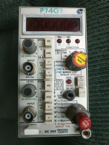
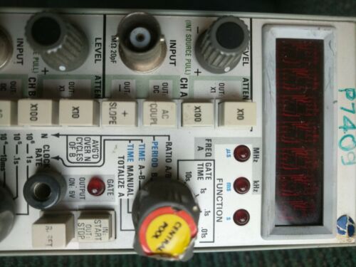
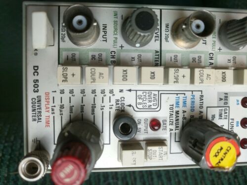
Tektronix DC 503 Dual Channel 100MHz Universal Counter FREE SHIPPING
$ 153.11
- Description
- Size Guide
Description
Tek DC503 Dual Channel 100MHz Universal Counter. Condition is Used. Working unit retired from Tektronix Video Division. Shipped with USPS Priority Mail.The DC 503 Universal Counter offers counting to 100 MHz and provides the versatility of six measurement functions: frequency, period, ratio, time A to B, time manual, and totalize. The two channels (A and B) have individual BNC inputs and separate trigger level, attenuator, and coupling mode controls. Seven-digit readout is via seven-segment light emitting diodes (LEDs) with automatically positioned decimal point; leading zeros (to the left of the most significant digit or decimal point) are blanked. A flashing display indicates register overflow. The DC 503 offers high performance in a variety of applications. Its interval measurement capability with selectable clock rates is useful for digital equipment design and maintenance, particularly digital control and data communications work. The A-channel frequency range of dc to 100 MHz serves in communication and rf use. High resolution measurements of low frequencies are available quickly in the period mode with averaging up to 1 million periods available. TIME MANUAL provides an electronic stop watch function with selectable clock rates. TOTALIZE counts and display the total number of input events at rates from dc to 100 MHz.
FREQUENCY MEASUREMENTS
FREQ A
To measure and display the frequency of a signal up to 100 MHz, set the FUNCTION switch to one of the shorter GATE TIMEs bracketed under the heading of FREQ A. make sure the LEVEL control is pushed in and connect the signal to the CH A INPUT. Set the DISPLAY TIME control ccw.
Triggering
The CH A LEVEL, Slope, Coupling, and ATTENuator controls all affect the ability to make a measurement. In general, the trigger controls are similar to oscilloscope controls, except that the end result is not a stable waveform graphic display, but a stable digital frequency display.
Coupling and SLOPE.
Use AC-coupling for most frequency measurements to avoid re-adjusting the LEVEL control for changing DC levels. The repetitive nature of frequency signals makes SLOPE selection insignificant.
Attenuators and LEVEL.
Signals between 300 mV and 5 V, peak-to-peak, should not be attenuated. For higher amplitude signals, select an attenuation factor such that the attenuated signal falls into the range of 500 mV to 5 V, peak-to-peak. The LEVEL control must be varied for a stable reading. It will not be touchy unless the signal amplitude and frequency are close to (or perhaps beyond) the specified limits.
A signal which looks stable on an oscilloscipe may still show jitter when measured with 7-digit resolution. If the count varies from reading to reading, it is probably due to jitter in the signal source. If the count changes unreasonably, the DC 503 is not being triggered properly, either because the controls are not set right or the signal is beyond the Counter's capabilities.
For frequency measurements, all CH B trigger settings have no effert. "N" or "CLOCK RATE" settings are irrelevant.
Measurement Intervals
To adjust the trigger controls, choose a short GATE TIME such as .1 s or .01 s. This gives rapid feedback via the display as to whether the Counter is being triggered or not. If it is, numbers will appear in the display. (If the frequency is below 100 Hz, numbers may not appear during the shortest gate times. For such low frequencies, a PERIOD measurement is better suited.)
Final selection of GATE TIME depends on the frequency being measured, desired resolution, and willingness of the operator to wait for a measurement. Using short gate times, higher frequencies may be measured, but at the expense of the greater resolution capabilities of the longer gate times.
Resolution.
A 10 s GATE TIME means the operator must wait 10 seconds for a measurement to be made and displayed. It is the only way to get best possible resolution and accuracy for signals below 1 MHz. Even then, a 10 second count will display fewer then the available 7 digits.
Overflow.
Through intentional use of "overflow" displays, it is possible to improve the resolution of the counter. Choose a GATE TIME which displays the most significant number of the measurement as far to the left as possible. Note the numbers displayed to the right of the decimal. Move the decimal point to the left by choosing longer GATE TIMEs until the desired resolution is achieved. The display will flash when the most significant number overflows the last storage register. Note that the increased resolution does not add to the accuracy of the measurement, except for quick A-B comparisons.
Measurement Rate
Once a stable measurement is obtained, the rate at which measurements are made can be controlled by the DISPLAY TIME control. Turning the control cw holds off the gate and stores the display for a longer time before a new measurement is made and displayed. DISPLAY TIME and GATE TIME together complete a measurement-display cycle.
The DISPLAY TIME control is uncalibrated and variable from about 0.1 s at the cw end. At the cw end, there is a detent position called HOLD. In HOLD, the last count taken will be stored and displayed for an indefinite time. A new count and display may be initiated by pushing the RESET button, turning the DISPLAY TIME control ccw, or changing to another GATE TIME.
PERIOD MEASUREMENTS
Gating
Period measurement is provided in universal counter-timers primarily to overcome a basic limitation of counters, i.e., the long time required to make a high resolution high accuracy measurement of low frequency signals. For example, a 1 kHz signal requires 1,000 seconds of GATE TIME to accumulate a million counts. However, in only one second, a 1 kHz signal can gate a count of one million clock pulses from a 1 MHz clock.
Simply stated, the PERIOD B mode reverses the functions of signal and clock as compared to the FREQ A mode. In FREQ A, the gate is held open for some number of clock pulses while signal events are counted, then displayed. In PERIOD B, the gate is held open for some number of signal events (N), while 1 μs clock pulses are counted, then displayed.
Averaging
Resolution and accuracy is increased by averaging the signal value over a large number of signal events. Increasing the selected number of N (AVG'D OVER N CYCLES OF B) increases the total time to take a measurement, similar to selecting a longer GATE TIME in the FREQ A mode. In general, the product of the signal period and the selected N factor should b 1 to < 10 seconds. The maximum period capacity is 9,999,999 μs. Therefore, a period X N product ≥ 10 s will cause an overflow. This means that the lowest frequency practical for period measurement is 0.1 Hz, even with N=1.
Low Frequencies
Period measurements of signals below 10 Hz, and particularly in the lowest decade from 0.1 Hz to 1.0 Hz, become rather sensitive to wave shape and amplitude. Since it is desirable for the signal to pass through the trigger hysteresis abruptly, square waves are preferred. Sine and triangle waves can be measured accurately at the very low end if the input amplitude is kept high so that the trigger input is driver hard. For repetitive signals below 0.1 Hz, use the TIME A to B mode.
CH B is the channel provided for period measurement; its bandwidth of 10 MHz is adequate for that purpose. For the higher frequencies, the frequency mode should be used. The CH B controls operate the same as the CH A controls. Because PERIOD B measurements may involve very low frequencies, the use of DC COUPLING will be more common than with CH A.
RATIO MEASUREMENTS
In the RATIO A/B mode, the frequency of the signal applied to CH A is divided by the frequency of the signal applied to CH B, and the resultant ratio is displayed. Note that the normal "frequency" mode is basically a ratio mode in which the ratio of the unknown signal to the internal clock is displayed. (Decade scaling of the internal clock and decimal point positioning normalizes the display relative to kHz or MHz units.)
Bandwidth Limitations
Because CH B has a bandwidth of only 10 MHz, it is not feasible to make ratio measurements of two signals, both well above 10 MHz. However, CH B will resplond to signals somewhat above 10 MHz if adequate signal amplitude is applied.
Triggering
The operation of CH A and CH B trigger controls is the same as for frequency and period measurement. In fact, since both channels must be triggered to obtain a display, it may be desirable to set the trigger controls independently. This may be accomplished as follows:
1) Go to the FREQ A mode and adjust the CH A trigger controls for a normal frequency measurement.
2) Go to the PERIOD B mode and adjust the CH B trigger controls for a normal period measurement.
3) Leaving CH A and CH B trigger controls as they were, go to the RATIO A/B mode. The correct ratio should be displayed.
The N/CLOCK RATE control may now be operated to select maximum resolution. For most measurements, the smallest value of "N" which produces a useful number of digits will be best.
TIME INTERVAL MEASUREMENTS
Electronic Start/Stop
The TIME A to B mode measures and displays the elapsed time interval between the triggering of CH A and the subsequent triggering of CH B. The triggering event does not have to be the same one for both channels. Separate events do not even have to be time related.
However, the most common application is to measure the width (duration) of a pulse, using opposite triggering slopes for each channel, rather than the frequency (or period) of a complete cycle.
For example, to set the gate duration of the RG 501 Ramp Generator accurately:
1) Apply the RG 501 gate (the triggering event) to both CH A and CH B at the same time. Set CH A to trigger on the + SLOPE and CH B on the - SLOPE.
2) Set the FUNCTION switch to FREQ A and adjust CH A LEVEL for a stable frequency display. Select PERIOD B and adjust CH B LEVEL for a stable time display. Do not change the SLOPE SETTINGS.
3) Set the FUNCTION switch to TIME A to B and select a CLOCK RATE for appropriate resolution.
4) When the RG 501 gate goes positive, CH A is triggered and the DC 503 gate opens, allowing internal clock pulses to be counted. When the RG 501 gate starts to return to zero, CH B is triggered, the DC 503 gate closes, and the accumulated count of clock pulses is displayed.
5) If the count is off the desired time interval, the operator can adjust the RG 501 controls until the required accuracy is achieved.
Single-Shot Using HOLD
Single-shot time intervals can be measured by putting the DISPLAY TIME control in HOLD. This will lock out both channels after CH A and CH B have been triggered, respectively. Pushing RESET clears the display and re-arms the trigger channels for another measurement.
GATE Output
The internal gate of the DC 503 is available at the front-panel GATE OUTPUT jack. Since it is coincident with the time interval measurement, it may be used with an oscilloscope to graphically relate the digital measurement to the analog signal.
MANUAL TIMING MEASUREMENTS
The TIME MANUAL position is a manual analog of the TIME A to B electronic mode. In this mode, only the CLOCK RATE switch and START/STOP switch affect the display.
Starting and Stopping
The TIME MANUAL mode may be thought of as a "stop-watch" type of operation. With the FUNCTION switch in the TIME MANUAL position, the display starts counting time-base pulses when the START/STOP button is pressed. It will continue to count and display the accumulated total until the START/STOP button is released. The last count will then be held in the diplay until another START command is given (in which case the count will again advance), or other controls are actuated. Pushing RESET will return the display to zero. Changing the setting of the CLOCK RATE switch will change the frequency of the time-base pulses being counted, and return the display to zero.
Clocking Rate
When the CLOCK RATE switch is in the 1 s position, one-second pulses are being counted, and the display accumulation advances one count per second, and so on. On the 1 μs position, the count accumulates at the rate of one million counts per second.
Whenever the accumulated count is greater than 9,999,999, the display will flash to indicate overflow; however, the accumulation continues at the normal rate, except that the digits for decades above 10
7
are not displayed.
TOTALIZING
Purpose
In the TOTALIZE A mode, signal events applied to CH A INPUT are counted and the accumulated total is displayed during the time the START/STOP button is pushed in. This mode is a manual analog of the frequency mode. It's main application is to accumulate a count of relatively infrequent and irregular events.
Operation
Apply the signal to CH A and set the trigger controls the same as for frequency measurement.
Starting the Count.
Press the START/STOP button in and adjust the CH A LEVEL control until a count begins to advance. The accumulated count is displayed in whole numbers. Only the CH A trigger controls, the RESET button, and the START/STOP button affect the display.
Stopping the Count.
If the START/STOP button is released and no other controls are operated, the last toal will continue to be displayed. No more incoming events will be added to the total.
Restarting and Resetting.
When the START is again depressed, incoming events will advance the displayed total. Resetting the count to zero can be done at any time by pressing the RESET button or by moving the FUNCTION switch to some other position, then back to TOTALIZE A.
above excerpt from DC 503 UNIVERSAL COUNTER Instruction Manual
